
LLC converters are a popular topology for PC, server, and TV power supplies due to their simplicity and efficiency. Its resonant operation enables soft switching over the full load range, making it ideal for high frequency and high power density designs. In addition, LLC converters use capacitive filters, eliminating the need for output filter inductors. With capacitive filters, LLC converters can also use lower voltage rated rectifiers, reducing system cost. In addition, the secondary-side rectifier enables zero-current conversion, greatly reducing reverse recovery losses. Taking advantage of the advantages of the LLC topology can further improve efficiency and reduce losses in the output rectifier.
Synchronous Rectifiers for LLC Resonant Converters
When using a diode rectifier, as shown in Figure 1, the full output current flows through the output diode. For low voltage or high output current applications, there is significant efficiency loss and thermal stress in these diode rectifiers.

If the diodes are modeled with a fixed forward voltage drop VF, the losses per rectifier diode can be estimated based on Equation 1. , calculated this way, for a 12V, 10A output design with a 0.5V forward voltage drop, each diode produces a loss of 2.5W, which means a total efficiency loss of about 4%.

Using a synchronous rectifier (SR) as shown in Figure 2, the voltage drop across the MOSFET can be much lower than the typical diode forward voltage.
For the same design, if the rectifier diode is replaced with a MOSFET, and with proper control, conduction losses can be calculated using Equation 2, and the secondary-side current shape is similar to the sinusoidal curve shown in Figure 3. Using 4 mΩ RDSon, each rectifier loss can be reduced to 0.247 W, which corresponds to a total efficiency loss of 0.4%.


The synchronous rectifier can be controlled by monitoring its drain-source voltage (VDS). Before the synchronous rectifier turns on, current flows through its body diode. The body diode forward voltage drop can be used to trigger the synchronous rectifier to turn on. After the synchronous rectifier is turned on, its on-resistance becomes the current sense resistor, and VDS can be used to sense the current to turn off the synchronous rectifier before the current reverses. Although the control method is very simple, there are still some design challenges for LLC resonant converter synchronous rectifier control.
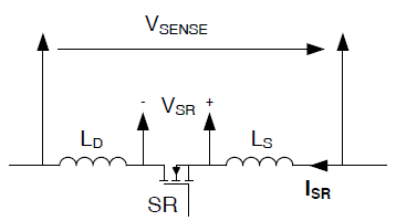
Synchronous Rectifier Turn-Off Time: The biggest challenge in LLC synchronous rectifier control is turning off the synchronous rectifier at the correct time. Unlike flyback converters, LLC synchronous rectifiers typically carry higher currents and have higher di/dt. As shown in Figure 4, the detection voltage VSENSE is used for synchronous rectifier control.
It includes the RDSon voltage drop (VSR) and the offset voltage across the package inductance (LD, LS) due to di/dt. For high di/dt and package inductance, this offset voltage can be large and the synchronous rectifier often turns off prematurely, resulting in longer body diode conduction time and larger conduction losses.
Burst Mode Operation: Another challenge associated with synchronous rectifiers used in LLC converters is burst mode operation. During burst mode, both primary side switches are turned off. The switch node capacitor resonates with the LLC transformer magnetizing inductor. This low frequency parasitic oscillation has the potential to falsely turn on the synchronous rectifier and cause the output to transfer energy to the primary side, which will cause more conduction losses.
Low Standby Power: Even though synchronous rectifiers save conduction losses, they can add additional losses to the system due to control circuit and gate driver losses. This additional loss is negligible at heavier loads due to the substantial conduction loss savings. However, under no-load conditions, the SR controller can be efficiently disabled by placing the SR controller in standby mode and using the SR body diode for rectification.
Reliability issue: Due to the capacitive filter, if both synchronous rectifiers conduct at the same time, the output will be shorted through the transformer and catastrophic failure is expected. It is critical to prevent both synchronous rectifiers from turning on at the same time, and even false triggering caused by circuit noise should be considered.
UCC24624 Synchronous Rectifier Controller for LLC Converters
To achieve better LLC resonant converter efficiency, the UCC24624 dual synchronous rectifier controller can be introduced for use with LLC controllers such as the UCC25360 series. The UCC24624 implements VDS detection for synchronous rectifier control, as well as various functions for LLC synchronous rectifier control challenges, making it an ideal solution for implementing high-efficiency LLC designs.
To address the challenge of early turn-off of synchronous rectifiers, the UCC24624 implements ratiometric gate drive, as well as an adjustable +10.5 mV turn-off threshold. The proportional gate drive reduces the synchronous rectifier gate voltage on the falling edge of the current. The reduced gate drive voltage increases the synchronous rectifier MOSFET RDSon, resulting in a higher voltage drop across the synchronous rectifier. This increased voltage drop exceeds the offset voltage caused by package inductance. Combined with a positive turn-off threshold, the UCC24624 minimizes body diode conduction time. To make packages with higher parasitic inductances such as TO-220 work better, the UCC24624 allows designers to further improve its turn-off by using an external offset resistor from the VSS pin to the source pin of the synchronous rectifier MOSFET threshold. This makes the controller less affected by the MOSFET package.

To improve burst mode operation , the UCC24624 uses an adaptive turn-on delay time in addition to the traditional shutdown blanking. During normal operation, the turn-on delay is kept low, reducing body diode conduction time and improving efficiency. During burst mode operation, the synchronous rectifier operation changes from a complementary mode to a transitionless mode. The UCC24624 can use this indication to detect whether the LLC has entered burst mode operation. This increases the turn-on delay time and helps suppress parasitic oscillations. The turn-on delay also increases under light load conditions to provide additional noise rejection. This feature of adaptive on-delay time helps suppress noise without sacrificing efficiency performance.
The UCC24624 also has a built-in automatic standby mode detection circuit that eliminates the need for external components. For LLC converters at no load, the converter operates in burst mode to regulate the output voltage. The LLC synchronous rectifier conduction time per switching cycle is still very long, while the average switching frequency of the converter is very low. The UCC24624 detects light load conditions based on the average switching frequency of the converter. It enables the controller to enter standby mode at no load, helping to achieve low standby power consumption.
To improve reliability and prevent both synchronous rectifiers from turning on at the same time, interlock logic is applied to both channels controlled by the synchronous rectifiers. During one channel's synchronous rectifier on-time, the other channel's synchronous rectifier is simultaneously disabled from conducting. Interlocking logic improves reliability of operation even when disturbed by system noise.
Article Source:https://mbb.eet-china.com/forum/topic/119196_1_1.html